BIM back capture Building Services Data Part 2 -Systems
In the first article here regarding capturing building services data on existing buildings, the focus was mainly on discrete components that sit in a system, with for instance lights, there may be an issue regarding which circuit they are linked to which switch or circuit fused in a sub-board, and this could easily be added to the component with a parameter in the family, rather than a looped line (may be difficult to show in a 3d view).
- Speed up the tedious stuff and enjoy designing and documentation more
- Works in all versions of Revit
- Information to PROVE your increased speed
But with services that are routed through the building such as heating and ventilation duct-work or pipework the routes and branches in the system are quite important. You need to know what parts are joined together, as, adjusting one air terminal may affect a number of other terminals on the same system.

With a system, there is usually some plant for pressurizing, filtering and tempering the supply air followed by duct-work linking this air to a number of spaces and then discharging the air. Along the way, as the branches split to different rooms, there are balancing dampers, also possibly fire dampers and access points if the duct passes through a fire cell. One a system has been designed and is operational it is very rare for duct-work to be removed and re-sized, if there is a problem with the duct being too small, it is usual to replace or speed up the fan to increase pressure in the system.
During its operational life, the main items that are maintained and adjusted are the plant such as filter, Heating/cooling coils/ Fan speed and balancing dampers and air discharge terminals. Duct sizes are not usually maintained (possibly cleaned on rare occasions), but routes and what they connect to are important.
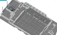
In the library example I initially started to draw the duct-work in 3D. Getting all the ducts and fittings correctly sized and connected was quite a long and tedious job, and I do not think it added value to the project and used up a lot of time. I then used model lines to describe the route of the duct-work and coloured it to show which system it belonged to.
I drew in plant and terminal and where balancing dampers and fire dampers were, as these would need to be accessed for maintenance purposes, their correct locations were important.

The 3D PDF of this system can be downloaded here
(remember to download and open 3d PDF to view)
This process could easily be used to quickly do site services on large sites such as University campuses in and around buildings. This could extend to power, 3 waters and any other services such as Data and security. The only limit in a single Revit model being the 30 mile radius in one file but you can use linked files to extend this distance I think. This would be a nice exercise to undertake.
The nice thing with building models quickly for AM/FM is that you can do something fast and effective the first time around to meet certain objectives, and at the end you still have the model. So if you want to initially draw lines for ducts and later it becomes important to draw all the duct-work in 3D then you just save the original model, make a copy and then draw the 3d duct and delete the original model lines. So the BIM has potential to evolve and become more data rich over time.
A few things that would be worth exploring further with this process:
- Drawing model lines in plane parallel with floor easy, doing vertical lines took me a bit of time. I need to find a method of speeding this up.
- Can you put parameters onto model lines? Do the lines need to be set on a specific category (Eg Generic Materials) or do you just place a family on that line?
- Is there a method to put duct sizes onto lines, using family or Tag?
- In the SimLab Soft PDF exporter, lines come out into the 3D PDF but there is a way to control their thickness?
How to use 3D PDF’s & Excel Macro’s to manage your assets part 3 of 3- Export from BIM

Wifi Scanner for Barcodes