BricsCAD SHAPE Lesson 2. Layers, Cutting/Joining Walls, Components, Fast Keys etc.
Continuing on with the process of test driving BricsCAD SHAPE by trying to Draw my House I came across another few challenges along the way.
In this post I will cover:
- Layers
- Cutting/Joining Walls & Floors
- Components- Windows and editing
- FastKeys and downloadable list of all BricsCAD keys
- Briefly Blocks, Materials & Printing
- Some end waffle you can skip
This product was only released this month and I’m sure there will be a few hiccups with the deployment of it.
A link to one resource first of all (another later):

A handy place to check on any little items you may find a challenge as their is not that much documentation specific tho SHAPE at the moment, but I’m sure that will grow.
First, you can freely Register for BricsCAD then you need to sign in to the Forum to add Comments or discussion topics. A useful place to pass around information.
After my challenges yesterday I posted 3 queries and got very quick responses, 2 of them solving issues for me, the other highlighting the difference between the Free SHAPE programme and the BricsCAD programme.
Carrying on from where I left off in the previous lesson.

I’d got the external walls as a box at correct height and width.
Units
Choose correct units imperial or metric, when you open a new drawing as I have yet to find a command to change the units once you are in the drawing. I scaled my image to metres rather than mm so had to do a bit of re-sizing later.
LAYERS
When you start a new drawing, there is usually only layer 0 and sometimes Layer: Defpoints.
Usually it is set to Layer 0.
Some people have the process of creating a specific layer first and then drawing on that layer.
My process is to draw the elements and then CREATE the layers you feel you need and then move objects to that specific layer. Draw first, then look at how you need to structure/differentiate/manage the information.
Inside Acad and other tools you have a MATCHPROPERTY command that you pick an object that has the correct layer/colour ect and then you match other objects to that. SHAPE has the Fastkey MA that does that.
I will just mention here Layer: Defpoints ( this is a dimension layer, when you pick the points for dimension ends it places DOTS at these points. To make them invisible Defpoints layer is invisible for Printing. In the old days this used to be a good layer to put your guide lines on as they didn’t show up.
So you end up drawing everything on Layer 0 which is a pain, so you need to move things around by putting them on to separate layers so that you can hide/show certain elements to make it easier to draw.
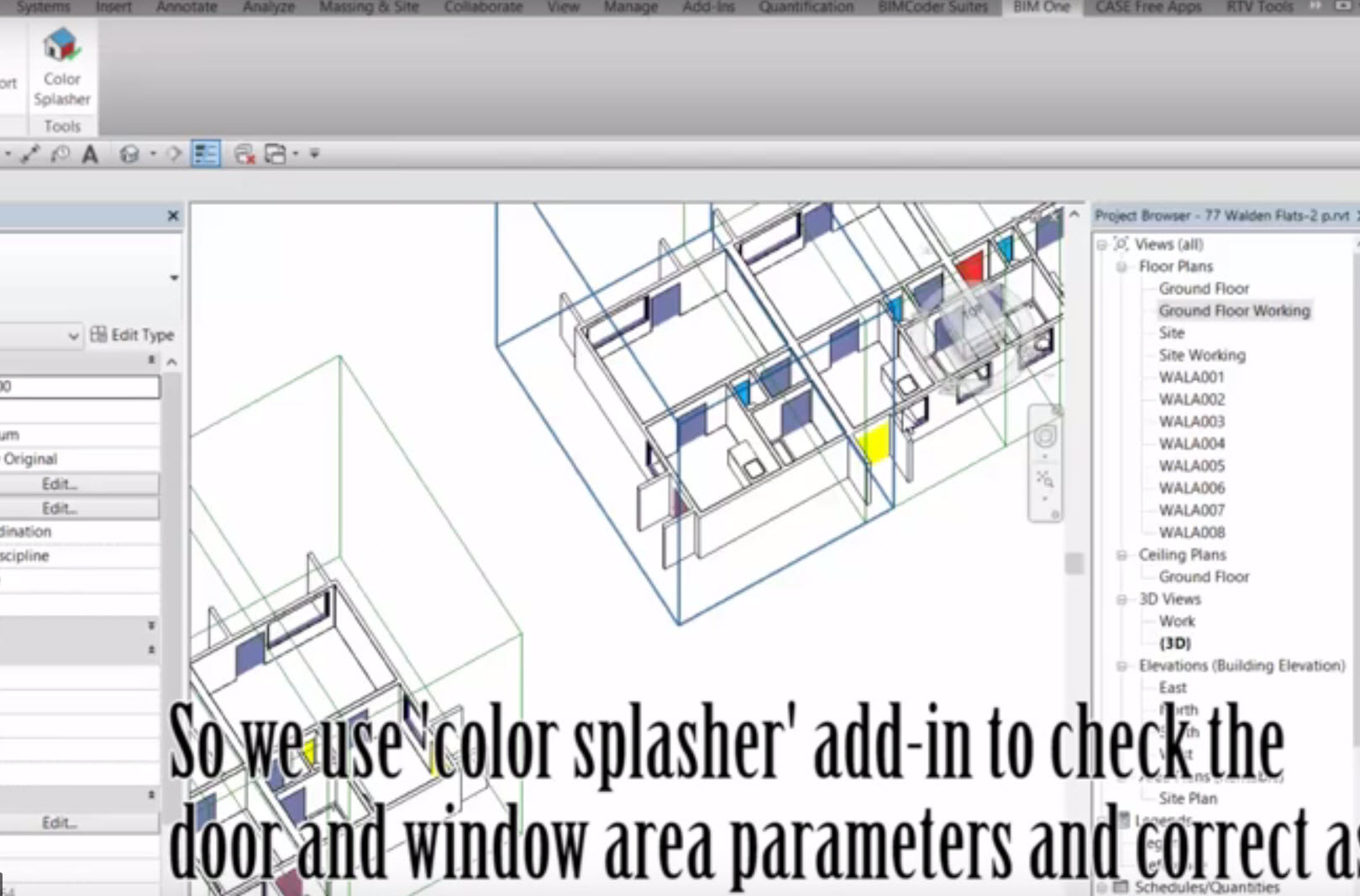
So in the image above , on the right hand side there is a layer area on the ribbon.
At the top of the pop out box there is a GREEN BUTTON for creating a NEW LAYER (item 1). You need to Click on it and Name the New Layer. It creates a layer Called NewLayer1 that it highlights. Write over what you want the new layer to be called. In the wall example, I’ve named the layer wall (so original) . You can click on the black box to the left of the name and change the colour of the layer. This is handy as if you draw another wall and its gray, you know you are still on layer: 0, whereas if the wall is Yellow then you know your current layer:wall.
The little blue dot to the left of the coloured boxes show which layer you are on. In the example above the current layer is set to layer:0 (item 2 in the image)
If you want to change it move your mouse to the layer that you want to be current layer, right click mouse and choose SET CURRENT. The blue dot will move to be beside that Layer.
To change the walls from Layer:0 to layer:wall you need to grab all the walls first. As they stick up above the ground plane I change my view so that I am looking horizontally across the floor
:-v (enter/spacebar) , 😮 (enter/spacebar) , :f(enter/spacebar) (front view I need this to make sure I do not pick the window)
Then make a window from Right to Left (this selects everything it touches (if you go the other way it only selects things totally inside the box)). See image below 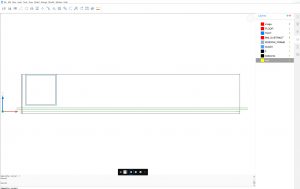
Then hover over the highlighted walls and change the layer that you want the walls to be on. 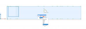
Pretty standard CAD stuff.
There are also commands like Layer Hide and layer Isolate (in Cad packages there are Layers Freeze and Layers thaw, not in this tool though- these make the layers stay off permanently unless you thaw them) . Maybe the Lock/Unlock does the same – see below.
At command line : -LA
:-layer [? to list/New layer/Make new current layer/Set layer as current/Color/Linetype/LineWeight/TRansparency/MATerial/Plot/stAte/turn layer ON/turn layer OFf/Freeze/Thaw/LOck/Unlock]
As you can see above there are a lot of options with layers that you can play with. Interesting that you could assign a Material to the layer.
Another point I want ot make about layers is COLOUR. You can color an Element on that layer by COLOUR, so select a color and whatever you have selected will go to that colour, or you can have all the elements on the layer COLOURBYLAYER. The colourbylayer means if you change the layer colour, every element that is COLOURBYLAYER will change to that new colour that you have chosen for the layer.
The Colour By Layer is brilliant if you are a Building Services Designer. You get the architects drawing, make everything colourbylayer and change all the colours to LIGHT GRAY, so the architectural Xref is light gray, if you need to highlight specific architectural elements that may impact on your design then you make them a darker gray. All your Ductwork will be in Vibrant colours of Reds/Blues/Magenta etc so your design stands out, and its located in the building properly so you can dimension off walls etc. So colourbylayer is brilliant for collaboration work.
Cutting & Joining Walls
As this programme creates 3 dimensional walls the 2d commands such as Fillet & Chamfer, trim , extend etc do not work. You have to use the 3D menu for that.
So on the menu bar there is one called MODEL, inside this there are 3 sub menu’s 3d Solids, 3d Solids Editing & Direct Modelling.
Since we have created the 3d object (the wall Box) we now need to draw/trace the internal walls and link them to the external walls. Also where the entry doors are, the doors are recessed, so we need to break and fillet those outer walls at the doorways.
So we can continue to use our method from the earlier lesson to draw the internal walls (at command line set height and width and then draw the walls (using enter/spacebar) at the end to say you want to stop that command. I just drew the walls into the outer walls, I was not too fussy with trying to make a neat intersection between the walls.
This type of tool at early design is about roughing out ideas, then tidying up afterwards. A sort of free-form process of thought, not getting bogged down in the finikity detail as that disrupts the thought flow. That is why confidence in using your tools to the point where the commands become second nature is important, it allows you to think of the design, not the tool.
So to tidy up the walls I have found:
- cutting into the wall. I have found there are 2 commands under the 3d Solids Editing sub-menu, SLICE & SPLIT. I found the SPLIT command worked ( FastKey (in future to be referenced as fk, also note that the fast-keys can be typed upper or lower case unless otherwise noted, I show upper case for highlighting them) is SPLI or BIMSP), for Slice (fk SLI).
NOTE. This does something weird if you have CONNECTED UP ALL THE WALLS as it takes a chainsaw right the way across the building, like a section line, so be AWARE.
For tidying up the walls I used UNION (fk UNI). Then I found that all the walls were connected together, so when you tried to move one wall across, all the walls moved together. Not what was intended.
I think I found a way of breaking one wall off then if it had a mitred corner with another wall, the mitre was split Then after moving it I had to rec0nnect them all again.
( I must point out here, I worked in the 2d cad environment for years, I didn’t really venture into the 3d CAD as I was more interested in Design/Documentation rather than front end presentation, then I moved to BIM, so some of this 3D Shape CAD has me a little disoriented).
So, to date, I have a method of Splitting & joining walls, not totally satisfactory at the moment, but I have the walls on my drawing, so I now move on to:
FLOOR
For the floor, I just used a Polyline that I drew on the base of the wall outline.
Menu DRAW, sub-menu LINE sub-menu Polyline (fk PL). I could also have used Rectangle (fk RECT) and just drawn a box. I think the pre-sets have a 0 in the Z axis so everything is drawn on the X/Y plane.
Once I had the polyline I used the Extrude tool (fk EXT) and selected the polyline and put in a dimension of -250 (250mm thk floor).
I also created a layer FLOOR, coloured RED and moved the floor element onto that layer.
So now onto:
COMPONENTS- Specifically Window
I had a few bumps along this path.
I followed the video for the process of inserting the window into the wall (drag and drop). Video HERE. I sized it as I placed it. All fine. Then I wanted to alter the window size.
Looking back at the tutorials, it tells about the Quad Cursor & Tips Video where you can get extra commands if you hover over specific items. So I tried that on the window.

I hovered over one of the items and it said Open Component for Editing. Cool , exactly what I wanted. So I clicked on it.
Alas, it calls a command _BMOPEN but it doesn’t recognise the command.
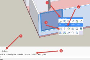
So I turned to the forum and laid out the issue.
A very nice gentleman got back to me with this:
Try using BIMREPOSITION instead. This command allows you to move the door/window around, and by pressing the Ctrl key you can change its overall size.
To MOVE multiple windows & doors, you can select them all first, then pick the MOVE option from the Quad.
You can also use BIMINSERT to make copies of an existing window & door.
Regards,
Jason Bourhill
And I tried that and it works fine. Thank you for the help Jason.
Because the window was cutting past the top of the wall, sometimes on re-sizing it does not heal and you have a gap above the wall left (I actually had this occur with a door in a different model) but in this case , as I moved it the wall healed over above the window which was great. I think you could possibly move it down and then move it up again.
(fk is BIMR) for BIMREPOSITION.
Fast Keys
I am just figuring a few of these out. I started talking about this is the previous lesson. They are a bit variable. So I also put up the issue on the forum.
This is the reply I got:
Shape uses the same command shortcuts and accelerators as the full version of BricsCAD. For a list of shortcuts I would take a look in the appendices of BricsCAD for AutoCAD users, or browse the online help for BricsCAD
Regards,
Jason Bourhill
And if you follow the link there are lots of goodies at the end of it.On first review of this I was very impressed with 1/ The FREE documentation that you can just go and grab (no registering etc) and 2/ the depth of the documentation for the BricsCAD for AutoCAD book.
Anyway I have trimmed the BricsCAD for AutoCAD book to the aforesaid appendices (less Tablet/Digitiser controls) and you can download HERE. This is all BricsCAD info, I’ve just culled the PDF. It is pretty extensive and also compares commands/variables to AutoCAD. As this covers the whole field of their programme range it has far too many commands that wont be in SHAPE. But a good basis to start to see what commands work and what their fast keys are.
So, again thank you BricsCAD and Jason for a really good resource to help people use your programmes.
Blocks & Materials. Preliminary Play
I had a brief fiddle with both of these. I will need to give them more attention later.
Blocks– I brought in an old block from acad with an attribute in it. On first visit it brings in the blocks and creates the layers for the blocks (if they have different layers). In SHAPE the attribute does not seem to work.This needs a bit more of an explore. ( My current thought is you create/populate attributes in DraftSight then bring the data back into SHAPE. Needs testing though).
Go to Menu INSERT/BLOCKS/INSERT BLOCKS to insert a block from a file ( you may have to create one using the SAVE BLOCK (that I will check another day). You can also type in FREE BLOCKS in your web browser. There are a lot out there on the interwongle.
Blocks are just Groups of elements, lines, circles , arcs etc, all grouped together into a mini-drawing with a .dwg extension, say a Table, a Chair etc, (or as in SHAPE windows and doors) that you can bring in and use time and time again.
Note, if you’ve brought blocks into your drawing and dont want them anymore, PURGE them out. This is extra baggage in the drawing file that you do not want and its good practice to have a cleanish drawing (no rubbish hidden in the file to bloat it and slow it down. Go to FILE/ DRAWING UTILITIES/PURGE and select BA(enter/spacebar)
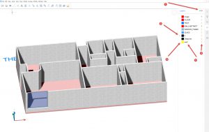
Materials– I f you look at the 3rd image in I did a drag/drop of a material onto the walls and the material went throughout the walls (on all surfaces). Now as I mentioned before, when I used UNION it joined all the walls together, so they are, as such, one component, so the material went throughout that one component. Apparently in the proper BricsCAD the material will only do a SURFACE, not the whole element/component.
I did post a query on the forum about 2 things for materials, the wrapping of the material over the whole object & also I wanted horizontal weatherboards, and how to get them into the material library. Not much joy on that one. Maybe some horizontal line materials will come in a later iteration.
Also , after playing with the model (to demo layers and moving walls onto different layers) 1/ The colourbylayer not working that well, 2/nor the material, that seems to have dissapeared. This will require some further investigation.
Printing
The last thing I want to just highlight in this post/lesson is printing.
You can print to PDF or PDF that’s your choice. Fair enough.
On menu line FILE/PRINT (fk CTRL P) and it pops up with a configurable dialogue box that you can fiddle with
I tried printing and I ended up selecting one of the paper sizes and it was in PORTRAIT MODE (most cad drgs are landscape) so I was a bit confused, as I was expecting a Sheet size to print to with a Portrait/Landscape Button. Not so, the Paper sizes are doubled up , some in Portrait configuration, some in Landscape Configuration.
Also you have the choice to make a Custom page size in the dialogue box. They appear at the top of the list which is great, so if you set up a Custom Landscape A4 (210 H x 297 w ) then its easy to find and use.
Again, this was something that confused me and I used the forum and Jason was very helpful with.
As this is a DWG file, you can just pull this model into DraftSight & print it in that programme to CAD line by colour or to CTB file etc.
Here endith this lesson.
Some End Thoughts & a ramble
This is a free programme and they are trying to limit it so that you move onto their paid programmes, which is fair enough. From what I have seen of this product so far I am really impressed.
It is definitely a good space to be in rather than the Autodesk environment. I am not impressed with how Autodesk are trying to force people into the subscription mode. That works for them, not their customers. Hopefully there will a lot of migration over to BricsCAD.
I was really interested in this article regarding Autodesks subscription model in comparison to how Adobe did it.
I personally have got used to BIM, and work in Revit. I would be interested in trying out BricsCAD BIM but a month is not long enough for me to test out all the things I need to find out about it before I have to pay for the programme.
As I’m interested in extending Designers services into the AM/FM field by data capture to aid Asset & Facilities Managers in populating and managing their asset registers not only would I need to learn BricsCAD BIM in a short period of time but to build and test model creation/data extraction processes too. A big ask in that time period. So that will have to wait for another day. Maybe after I have get a job and can afford to tinker with it.
So far, the things that I like about BricsCAD SHAPE are:
1/ It is the Basis of the rest of their products. So you can transfer from the cut-down version and develop further in more productive tools. WITHOUT LOSS OF INFORMATION.
2/ People coming from a CAD background will be comfortable with the commands and the command line.
3/ Beginners in the space have more mouse/key combination variables like SketchUp (not my space, but good to offer people from that background)
BIM to BricsCAD?
Not sure. In BIM you have elements of Walls, Floors, Ducts etc. They are the things you build with. So data extraction is by category which will always be the same. So you have all the aspects off the Building Entity as long as you classify by category. This has come with its challenges when I looked at some bridges that were modeled in BIM, the road surface was a roof, not a road as you needed the camber. Also in Revit it has a 20Km radius, so not that great for infrastructure projects.
Also, CAD to BIM was a steep learning curve for me as I had 20 years of CAD. I suppose for people in the BIM environment who have not been in the CAD environment, they may find the transition to CAD quite hard too.
In CAD elements are whatever you want to call the Layer they are on. Far more flexible. Great for infrastructure as there are no bounds. The CAD environment does not have the constraints of the more specialised BIM modelling programmes. I need to do some research on how they manage the BIM part in BricsCAD.
Anyway, enough waffle, I hope this overview of some of the processes in BricsCAD SHAPE is of use to you and it gets you using it proficiently and effectively.
kind regards
Max Drake
[IF YOU ENJOYED THIS POST COULD YOU PLEASE EITHER CLICK THE LIKE IT BUTTON IN LINKEDIN OR SHARE IT WITH YOUR COLLEAGUES. THANK YOU. IT WILL MOTIVATE ME TO WRITE SIMILAR ONES]
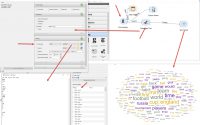
Orange 3. Text Mining basic exploration
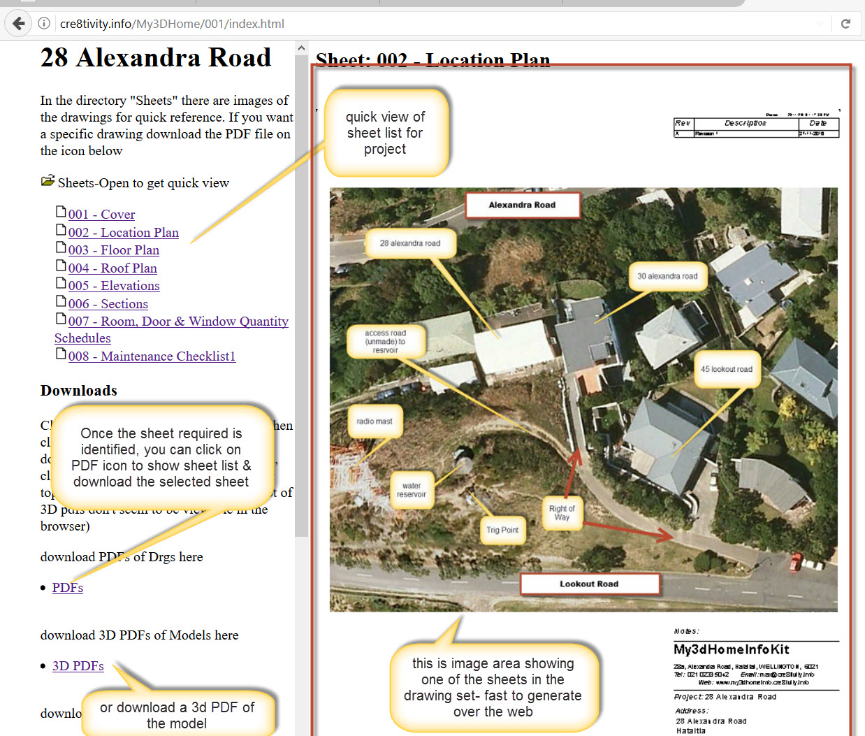
Quick Drawing access anywhere online with PDF download