Free BricsCAD SHAPE Lesson 1. Basic walls, command line, underlays, orthographic & views.
There is a video on YouTube that demo’s the use of BricsCAD SHAPE, it is here:
I’m always suspicious of a video putting the programme through its paces as they always make it look TOO EASY, when in fact, when you come to grips with the tool its bloody complicated, or slow or just plain difficult. Obviously they are trying to show how the programme can fly and are accentuating the positive but it does usually sucker me in to try the programme to get frustrated.
After my initial enthusiasm of the product, and it is pretty cool, I girded my loins to try and produce something I wanted to do rather than fiddle with it.
And got Really FRUSTRATED. You need to lefty click , right click and TAB and then use Ctrl to align wall Left/Centre/Right!! Great if you are using the tool all the time but TOUGH otherwise.
Step back a minute.
There are really short Videos (21 of them) showing you step by step lessons on basic use of tool.
There is also a little blurb showing the steps (they are in appendix at the bottom of the page, with links to the video page at bottom).
All good but complicated, especially if you are used to CAD or BIM environment. The lessons are based on someone coming over from SketchUp to BricsCAD SHAPE. But if you are used to the CAD environment you are used to the Command Line showing you whats happening.
After fiddling around with BricsCAD SHAPE for a while ( and not being able to do a stepped wall 2400mm high x 100mm wide as all the key commands ( Ctrl, Enter, Left Mouse Click, Right Mouse Click & TAB are all over the keyboard/mouse controls)) and I’m a Lefty, so even more irritating. Also there do not seem to be any ways to adjust/tailor the keys to your preference (more about that later).
I came across this:
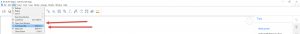
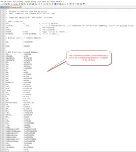
 Hurray, hurray, the command line. This is what I’m used to in Acad and other CAD programmes. Fantastic.
So now we can see how the commands function.
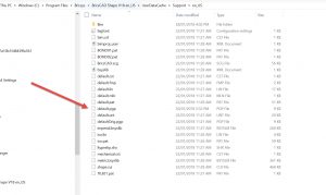
I also did a search for a .PGP file and guess what, there is one , under the directory shown below. Very exciting, except most don’t work & even editing it and rebooting does not effect any change.
So what this leads me to conclude is that this is a CUT DOWN version of their CAD package. Fair enough. They are trying to attract people to user their free package to get exposure and possibly move on to their Paid packages. A good marketing ploy.
Thank you BricsCAD for the opportunity to try your product, I think it is a cool tool.
What this means to me is that this is a CAD package, like Autocad LT that has been re-packaged to appear like SketchUp.
And as a SketchUp lookalike is trying to make the controls similar to SketchUp. That doesn’t really work for me. But the Command Line Does.
I found the tutorial video method on setting up Wall length, Height & Width very difficult to do. My dexterity and habits got in the way , as well as the setout of the keys required to do the operations. ( follow videos 2 & 3 and see how you do).
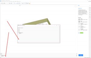
With the command line showing ( a simple SHIFT + F3 toggles on /off) you can set the height, set the width, then draw the wall. That would be the normal CAD process. So you only have to concern yourself will drawing the wall lines in plan.
So the command prompt shows:
: _shape ( from clicking on icon in top left of screen)
Start point or [Height/Width/Justification/Entity/Separate solids/Dynamic] <Entity>:h
Height of shape <2400>: 2400
Start point or [Height/Width/Justification/Entity/Separate solids/Dynamic] <Entity>:w
Width of shape <100>: 100
Start point or [Height/Width/Justification/Entity/Separate solids/Dynamic] <Entity>: (I start drawing lines with mouse click here)
Set next point or [draw Arcs/Distance]: (all clicks of mouse)
Set next point or [draw Arcs/Distance/Follow/Undo]: (all clicks of mouse)
Set next point or [draw Arcs/Close/Distance/Follow/Undo]: Etc , Etc
Then Press ENTER or SPACEBAR (which is the same as ENTER) to complete the command
So this is pure joy. Basic autocad commands and using spacebar for ENTER.
Also drawing lines in 3D is the same.
Click on a point on the drawing (start point of LINE or POLYLINE, then use @ 100, 100, 100 ENTER ( to give another point which is 100(X direction), 100(Y direction), 100(Z direction) from the first point. All standard stuff. IO love it.
In the PGP file you can see residual commands that have not carried over to the programme, viewports & dimensions (there is a measure tool though, which is handy).
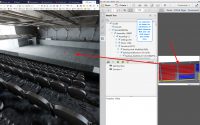
the other nice things is Underlays using IMAGES. I am tracing over a floor plan which I had in PDF format and changed it to a JPG (using Snagit) and then imported it and scaled it. So now its a trace.
I am trying to work in my usual method of workflow (box and then do different walls and fillet (not sure how that will go yet)

A few more little things I have found:
VIEWS
: -V
View [? to list/Delete/Orthographic/Restore/Save/Window]:o
Enter an option [Top/Bottom/Front/BAck/Left/RIght] <Top>:t
This sets your view looking down on plan (great for tracing over underlay)
ORTHOGRAPHIC MODE
Also, when clicking from point to point with mouse, to keep it in ORTHOGRAPHIC (ie all lines at 90 degrees to each other) just hold down the SHIFT KEY
END COMMENTS
So, to date, I’m really liking this tool. Its more like a cad package than a Sketch package.
I was also playing with SketchUp MAKE and tried doing the same exercise. The Doors and windows are not as easy to do.
Also, looking at the components, I think if you have a BLOCK library they will most probably work (yet to test out). The Component library will let you look outside on your computer, so potentially you can pull in external blocks (and I need to explore blocks with attributes too).
I also looked at materials, this is not an area of my personal expertise. The first material I wanted to use was HORIZONTAL TIMBER WEATHERBOARDS and I could not see them in the Material library, nor could I see how to alter an existing material to make it look like HORIZONTAL TIMBER WEATHERBOARDS. So the materials library still needs a bit more exploring.
So after a couple of days messing with the programme, I can put a JPG plan underlay into the space, to scale. Create walls of a controlled thickness and height in the location I want them, and have learned a few shortcut keys. Not fantastic , but I am pleased with 1/ my progress, 2/ The sophistication of the tool.
So thank you again BricsCAD. Maybe a CAD persons tutorial would also be good with some fast keys.
[IF YOU ENJOYED THIS POST COULD YOU PLEASE EITHER CLICK THE LIKE IT BUTTON OR SHARE IT WITH YOUR COLLEAGUES. THANK YOU. IT WILL MOTIVATE ME TO WRITE SIMILAR ONES]
Appendix – BricsCAD SHAPE lessons and Key Controls
2 The Shape tool is used to create walls
Select the start point of the wall. Move the cursor to the next point, and left-click it. You can continue creating joined wall segments. Simply right-click your mouse, or press ENTER, to stop creating additional wall segments.
Move your cursor up to set the wall height, or type in a value.
Right-click to accept the default wall width, or press the TAB key to type in a new value. Values you enter here become the new defaults for wall height and width.
In Shape, it’s easy to use new or existing linework as a guide. The cursor snaps to line endpoints automatically. The TOOLTIP at the bottom of the screen reminds you to press the CTRL key to cycle through the wall justification options: left, center or right.
From <https://blog.bricsys.com/shape-basics-create-walls/>
3 Layouts in BricsCAD Shape
You will use the Shape tool. (Button Top Left on top Ribbon, looks like an “L” wall)
Select your start point, move the cursor to the next point and left-click again.
Shape automatically creates wall connections. Press the enter key or right-click once to accept.
You can move your cursor to set the wall height, or simply type in a new height.
Then, you can press the TAB key to change the width, or just right-click to accept the default value.
You can also use an existing 2D plan to start your layout.
Use the Shape tool. Press E, for “Entity” and select the outside border.
Move up to set the height, type in a value, or right-click to accept the default value.
You can press the CTRL key to cycle through the wall justification options: left, center or right.
From <https://blog.bricsys.com/shape-basics-create-layouts/>
4 How to select elements
Model elements in BricsCAD Shape are solids. They are made up of edges and faces. You can select faces by moving your cursor over the face and left-clicking your mouse. Press the ESC key to clear your selection.
You can select edges by moving your cursor over the edge. Then press & hold CTRL and left-click your mouse.To select an entire solid, move the cursor over any face of the solid, press & hold CTRL and left-click your mouse.
To select multiple faces, just left-click them, one-by-one. To select multiple edges or multiple solids, press & hold CTRL and left-click them, one-by-one.
Sometimes, the element or elements you want to select are hidden behind others. To select hidden elements, press the TAB key while hovering over the element. Each time you press TAB, you’ll cycle to the next element underneath the cursor.
When the element you want is highlighted, just left-click to select it.
From <https://blog.bricsys.com/shape-basics-select-elements/>
5 Selection boxes
You can select multiple model elements using a selection box. By default, selection boxes see and select entire solids.
If you press the CTRL key ONCE while the selection box is active, you will only see faces. The tooltip at the bottom of the screen shows these different modes. The CTRL key cycles between these modes. If you press CTRL once more, you will only see edges.
Draw a selection box from left to right, it will display in blue. Blue selection boxes will only see elements that are completely inside the box. Draw a selection box from right to left, it will display in green. Green selection boxes will see all elements that lie inside the box, AND all elements that cross the boundaries of the box.
From <https://blog.bricsys.com/shape-basics-selection-box/>
6 How to detect boundaries
BricsCAD Shape automatically detects and highlights closed boundaries, as you hover over different model elements. When a boundary is detected, it will be highlighted. To select it, just left-click inside the highlighted boundary.
After you select a boundary, you can use it to create new elements or modify existing elements. Remember, if you don’t want to select the boundary but for example the face or the solid, just press TAB until the element you want is highlighted.
From <https://blog.bricsys.com/shape-basics-detect-boundaries/>
7 Quad cursor and rollover tips
In BricsCAD Shape, the user interface includes everything that you need and nothing that you don’t. Hover over a model element, and a Rollover Tip will display that element’s properties. Different types of elements will display different property sets.
The Quad cursor is a context-sensitive tool panel. Right-click on any empty space on your screen, and you’ll see the Quad in its “No Selection” state. Move your cursor onto the displayed icon, and the Quad expands. The most relevant commands are on the top bar, and the pulldowns will show all available commands by category.
Next, move your cursor over any model element. The Rollover Tip will appear. Then, move your cursor onto the Rollover Tip. The Quad opens, and shows you the tools that you can use on the selected element.
From <https://blog.bricsys.com/shape-basics-quad-cursor-rollover-tips/>
8 Connecting walls is easy
Select two walls, raise the Quad and click the “CONNECT” tool. The TOOLTIP at the bottom of your screen reminds you that there are different connection options available.You can cycle through the three connection options by pressing the CTRL key.
We can use the CONNECT tool to connect disjoint walls. Highlight any face, and the “Connect with Nearest” tool makes it happen.
From <https://blog.bricsys.com/shape-basics-wall-connections/>
9 Drag in BricsCAD Shape
Drag is a smart direct modelling tool with many uses. Drag lets you change the height and width of walls easily. The TOOLTIP appears to remind you that you have options… Pressing the CTRL key connects the wall’s selected face to the nearest model element.
Next, select a major wall face, and Drag’s default behavior lets you move the wall. Press the CTRL key, and you can change the overall depth of the wall. When pressed TWICE, you’ll create a copy of the wall. You can create additional copies by pressing the “R” key.
When multiple walls are connected, the power of Drag increases. The CTRL key allows moves, width changes and copies, and the TOOLTIP appears to remind you of these options.
As your model evolves, Drag gets smarter. Here, the only valid Drag option is “copy”, and this becomes the default behavior.
From <https://blog.bricsys.com/shape-basics-drag/>
10 Push/Pull in BricsCAD Shape
Push/Pull is a basic modelling tool. It’s a local editor for single solids. Push/Pull requires a positive distance and a direction. It won’t let you create a void.
Move in the positive direction, and push/pull lets us increase the width of this solid.
Simplicity is power with push/pull editing in BricsCAD Shape.
From <https://blog.bricsys.com/shape-basics-push-pull/>
11 Extrude
The EXTRUDE tool creates 3D elements from 2D line work.
You can EXTRUDE a selected boundary, for example, to create a floor slab between existing walls.
EXTRUDE can subtract geometry, also. Note the TOOLTIP that appears, reminding you of the CTRL key options for the tool.
Pressing the CTRL key cycles through all of the available EXTRUDE options.
From <https://blog.bricsys.com/shape-basics-extrude/>
12 Manipulator tool in BricsCAD Shape
The manipulator is a visual tool that rotates, moves, or mirrors solid elements, around or along a single axis.
Press and hold the CTRL key, move the cursor to the element of choice and left-click. By holding down the left mouse button slightly longer, the manipulator should appear. Move the cursor onto one of the three manipulator arcs and left-click to rotate your solid. Then, move the cursor onto one of the three axis shafts and left-click for a constrained move along that axis.
To move your selection in 2D, constrained to a plane, left-click one of the three white plane indicators.
To mirror your selected solid, left-click one of the blue axis arrows.
Precise manipulation is always available through the manipulator’s dynamic dimensions. You can rotate and re-locate the manipulator on the selected solid by left-clicking on the white orientation dots.
From <https://blog.bricsys.com/shape-basics-manipulator/>
13 Components
You can drag and drop content from the right-side panel directly into your BricsCAD Shape session. Open the component library by left-clicking the “hot-air balloon” icon. It is located on the vertical toolbar, on the right-hand edge of your screen. The pull-down list box shows the component categories. Left-click on the category name to select it, or search for specific types of components in the Search box.
Let’s place some furniture in our model. To select a component from the panel, hover the cursor over the component that you want to use, then click and hold the left mouse button. Next, simply drag the component into your model. Move it to the desired position and release the left mouse button. Hover over the icon, left-click and hold.
From <https://blog.bricsys.com/shape-basics-components/>
14 Windows and doors
BricsCAD Shape includes a collection of doors and windows in the components library.
Open the components library by left-clicking the “hot-air balloon” icon. It is located on the vertical toolbar, on the right-hand edge of your screen.
Select “Doors” from the pull-down list box.
To select a door from the panel, hover the cursor over the door that you want to insert, then click and hold the left-mouse button.
Drag the door onto a wall.
When releasing the left mouse button, you will be able to position the window in the wall precisely using Dynamic Dimensions. You can enter a precise value for a distance, or press TAB to go to the next value.
The TOOLTIP at the bottom of your screen reminds you of your options. Press CTRL to toggle between door positioning and door size. Enter the desired values for the height and width of the door by pressing the TAB key. When you’re done sizing and placing the door, press the ENTER key.
This is the same for a window. Change “Doors” to “Window” in the pull-down list box. Drag a window into the wall. You can change the size and location of a window just as you did with the door.
From <https://blog.bricsys.com/shape-basics-windows-doors/>
15 Create a custom window
You can create custom windows easily in BricsCAD Shape.
Use the POLYLINE tool to draw the outline of the window on the wall face.
Use the POLYGON tool to draw the outline of the window on the wall face.
Use the RECTANGLE tool to draw the outline of the window on the wall face.
Move the cursor inside the window outline and, when the boundary is highlighted, choose “CREATE WINDOW” from the Quad. The available window styles are shown in a dialog box. Move your cursor over the window design of your choice, and left-click it. The window is automatically created.
You can create a custom window from a wall boundary. Select face of the outer wall and use the “OFFSET” tool from the Quad. Move the cursor to re-size the new boundary, or key in a value and press ENTER. Then, highlight the offset boundary and select “CREATE WINDOW” from the Quad.
Once again, the available window styles are shown in a dialog box.
From <https://blog.bricsys.com/shape-basics-custom-window/>
16 Materials in BricsCAD Shape
BricsCAD Shape includes a collection of materials and color swatches in the materials library. Open the materials library by left-clicking the “paintbrush” icon. It is located on the vertical toolbar, on the right-hand edge of your screen.
To assign a material to an element in your model, hover the cursor over the material or color swatch that you want to insert, then click and hold the left-mouse button. Drag the material onto the model element, and release the mouse button.
You can filter by selecting a category from the drop-down list It is possible to apply a material to multiple elements at once by preselecting them
From <https://blog.bricsys.com/shape-basics-materials/>
17 Layers in BricsCAD Shape
Using layers to group model elements is a time-tested way to organize 3D models. Open the Layer panel by left-clicking the “stacked sheets” icon. It is located on the vertical toolbar, on the right-hand edge of your screen. Turn layers on and off in the Layer Panel. Do this by moving the cursor over the lightbulb icon to the right of each layer name, and left-clicking the mouse.
Toggling layers is a simple way to isolate model elements, to help with navigation and viewing. You can create a new layer by left-clicking the green “plus sign” at the top of the layer panel. The current layer is indicated by the blue dot, shown in the column to the left of the layer names. To change the current layer, just left-click in that column.
From <https://blog.bricsys.com/shape-basics-layers/>
18 Hiding and isolating objects
When model elements block your view, you can HIDE them easily. To hide one or more elements, just highlight them, raise the Quad and left-click ‘Hide Entities’.
The opposite of hiding an element is isolating it. Highlighting one or more entities, and selecting ‘Isolate Entities’ from the Quad will hide all the non-highlighted elements in your model.
Hiding and Isolating are temporary functions that you can use to simplify your model while working on it. When you want to see all the elements in your model, just raise the “No Selection” Quad and left-click “Show Entities”.
From <https://blog.bricsys.com/shape-basics-hiding-isolating-objects/>
19 Sections
You can use Sections to cut through your model dynamically. A Section can be created by opening the Quad and left-clicking ‘define section’, found under the Model tab.
Then, selecting any solid face in your model will create the Section, parallel to the selected solid face. If you don’t choose a surface to attach the Section, a horizontal Section plane will be created.
A Section can be toggled on and off by double-left-clicking its handle, or by highlighting the Section plane and using ‘Clip Display’ from the Quad. A Section element has three grip edit points. Selecting the Section’s handle turns the grips on for editing.
You can move the start and end grips to change the orientation and width of the Section. You can move the midpoint grip to reposition the section plane. If you left-click the arrow displayed near the midpoint grip, you will flip the clipping direction of the Section.
From <https://blog.bricsys.com/shape-basics-sections/>
20 Visual Styles
BricsCAD Shape uses Visual Styles to control the appearance of your model.
Open the Visual Styles panel by left-clicking the “camera” icon, located on the vertical toolbar, on the right-hand edge of your screen. Each defined Visual Style, when selected, will change the look of your entire model.
In the Visual Styles panel, you can change the perspective view. Moving the perspective slider all the way to the left will turn perspective off. The Quality slider controls the on-screen rendering quality of your model.
From <https://blog.bricsys.com/shape-basics-visual-styles/>
21 Structural profiles
BricsCAD Shape offers standard structural steel profiles to speed the creation of structural elements. Included are American, British and European standards. Use the Profile tool to create a beam or a column.
Select the start point of the column. Move the cursor to the next point and left-click, or type in a value and press Enter. Continue to create elements, or press enter when you’re done.
You can change the profile using the Profile panel. Open the profile panel by left-clicking the “profile” icon. It is located on the vertical toolbar, on the right-hand edge of your screen.
Select a standard and choose a profile. You can also search for specific profiles. To select a profile, hover over profile you want, then click and hold the left mouse button. Drag the profile into the beam or column and release the left mouse button. To connect elements, select them, raise the quad and use the Connect tool, found on the Model tab. You can toggle between different connection types by pressing the CTRL key.
You can also create your own profiles from scratch.
We’ll draw a square, and offset it a given distance to create the new profile shape. To change the profile of an existing beam, select the beam and use “apply profile” from the quad. Select the new profile. The beam shape updates. Press enter to apply the change.
Left-click to place the component, or use Dynamic Dimensions to precisely position it. You can enter a precise value for a distance, or press TAB to go to the next value. Press enter to accept the final position.
From <https://blog.bricsys.com/shape-basics-structural-profiles/>
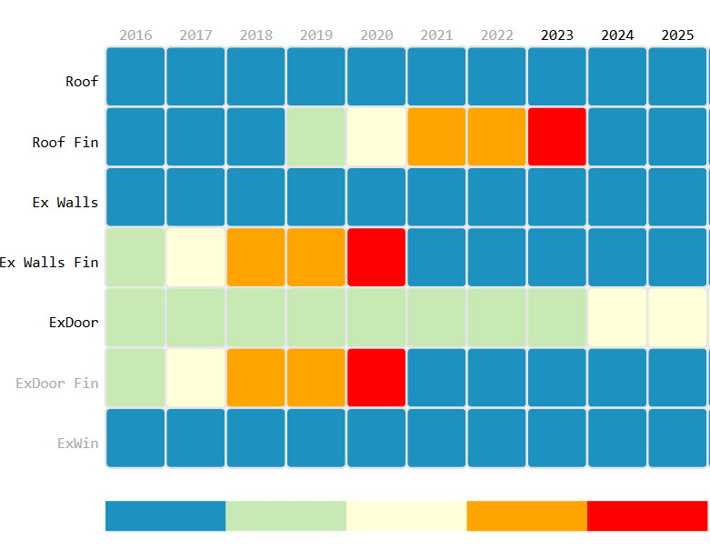
Heatmaps for visualising exterior and interior space conditions
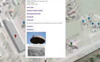
How to use Maps to find Data on Assets